Couplings and Backstops Manufacturing Processes: Ensuring Efficient Power Transmission
Couplings and backstops are essential components used in various industries for efficient power transmission and motion control. They play a crucial role in connecting rotating shafts, absorbing misalignment, and preventing reverse rotation. The manufacturing of couplings and backstops involves precise processes to ensure durability, reliability, and optimal performance. In this blog post, we will explore the key steps involved in couplings and backstops manufacturing processes.
1. Design and Engineering: The manufacturing process begins with the design and engineering phase. Coupling and backstop designers utilize CAD software and advanced engineering principles to create detailed designs. The design process involves considering factors such as torque capacity, misalignment compensation, operating conditions, and specific industry requirements.
2. Material Selection: Choosing the right materials for couplings and backstops is crucial to ensure strength, durability, and performance. Common materials used for manufacturing include alloy steels, stainless steels, and various engineering plastics. The material selection is based on factors such as torque capacity, operating conditions (including temperature and corrosive environments), and cost considerations.
3. Machining and Fabrication: Once the design is finalized, the manufacturing process begins with machining and fabrication. This involves shaping and forming the coupling or backstop components through processes such as milling, turning, drilling, and grinding. CNC machines are often used to ensure precision and consistency in the manufacturing process.
4. Heat Treatment and Surface Treatment: Couplings and backstops often undergo heat treatment processes to enhance their mechanical properties. Heat treatment techniques such as quenching and tempering are employed to achieve the desired hardness, toughness, and wear resistance. Surface treatment methods such as coating or plating may also be applied to provide additional protection against corrosion and wear.
5. Assembly and Balancing: Once the individual components are manufactured and treated, they are assembled to create the complete coupling or backstop mechanism. Assembly involves precise fitting and alignment of the components to ensure smooth operation and optimal performance. Balancing is also performed to minimize vibration and ensure stable operation at high rotational speeds.
6. Testing and Quality Control: Couplings and backstops undergo rigorous testing and quality control measures to ensure their performance and reliability. Functional tests, including torque testing, misalignment testing, and endurance testing, are conducted to verify the components’ ability to handle specified loads and operating conditions. Quality control inspections, including dimensional checks and surface finish evaluations, are performed to ensure adherence to design specifications and standards.
7. Packaging and Delivery: After testing and quality control, the couplings and backstops are properly packaged to ensure protection during transportation and storage. Packaging materials and methods are chosen to safeguard the components and prevent any damage during handling and shipping. The products are then delivered to the customers or integrated into larger systems or machinery.
The manufacturing of couplings and backstops involves a series of precise processes to ensure durability, reliability, and efficient power transmission. From design and material selection to machining, heat treatment, assembly, and quality control, each step plays a vital role in producing high-quality components. By following stringent manufacturing processes and adhering to quality control measures, manufacturers can deliver couplings and backstops that meet the performance requirements and specifications of various industries.

Gear Couplings
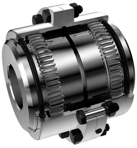
Gear couplings are a type of flexible coupling used to connect two rotating shafts, allowing for a smooth transfer of power and torque between them. They consist of two gear teeth, one on each shaft, which mesh together to transmit power from one shaft to the other. Gear couplings are widely used in various applications, including steel mills, paper mills, and other heavy industries where high torque and precision are required.
In this blog post, we’ll take a closer look at gear couplings, how they work, their advantages, and their applications.
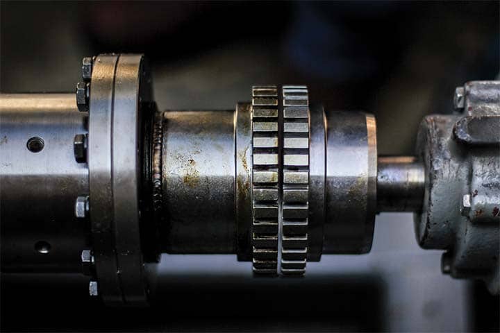
How Gear Couplings Work: Gear couplings consist of two hubs with external teeth thatmesh together to transmit power. The hubs are made of high-strength steel and aredesigned to withstand high torque and loads. The hubs are connected by a flexible sleevethat compensates for misalignment and absorbs shock loads.
The flexible sleeve can be made of different materials, including metallic, non-metallic, and composite materials. The most commonly used material for the flexible sleeve is metallic, which is made of stainless steel, bronze, or other alloys. Non-metallic sleevescan also be used in some applications, such as food processing or pharmaceuticals, where contamination is a concern.
Gear couplings work by transmitting torque through the meshing of the external teethon the hubs. The teeth are cut to precision to ensure proper alignment and reduce wearand tear. Gear couplings can accommodate different types of misalignments, includingangular, radial, and axial misalignments. This makes them ideal for applications wherehigh torque and precision are required.
Advantages of Gear Couplings:
Gear couplings offer several advantages over othertypes of couplings. These include:
Applications of Gear Couplings:
Gear couplings are used in various applications, including:
Conclusion: Gear couplings are a type of flexible coupling widely used in heavyindustrial applications where high torque and precision are required. They offer severaladvantages over other types of couplings, including high torque capacity, high precision, flexibility, durability, and easy maintenance. Gear couplings are used in variousapplications, including steel mills, paper mills, chemical plants, and marine applications.

Fluid Couplings
Fluid couplings are a type of hydraulic coupling used to transmit power and torque between two rotating shafts. They consist of an impeller and a runner, both of which areen closed in a housing filled with hydraulic fluid. Fluid couplings are widely used in various applications, including mining, cement, and power generation, where they offer high efficiency and smooth power transmission.
In this blog post, we’ll take a closer look at fluid couplings, how they work, their advantages, and their applications.
How Fluid Couplings Work: Fluid couplings work on the principle of hydraulic torquemultiplication. The impeller, which is connected to the driving shaft, rotates and createsa flow of hydraulic fluid inside the housing. The hydraulic fluid then transfers torque tothe runner, which is connected to the driven shaft.
Fluid couplings use hydraulic fluid to transfer torque and allow for a smooth start andstop of the driven equipment. The hydraulic fluid in the coupling also acts as a damping mechanism, reducing shock loads and vibrations during operation.
Fluid couplings have three main components: the impeller, the runner, and the housing. The impeller is the driving component and is connected to the driving shaft. The runneris the driven component and is connected to the driven shaft. The housing encloses theimpeller and runner and contains the hydraulic fluid.
Advantages of Fluid Couplings:
Fluid couplings offer several advantages over othertypes of couplings. These include:
Applications of Fluid Couplings:
Fluid couplings are used in various applications, including:
Conclusion: Fluid couplings are a type of hydraulic coupling widely used in variousapplications, including mining, cement, and power generation. They offer severaladvantages over other types of couplings, including smooth power transmission, highefficiency, overload protection, low maintenance, and flexibility. Fluid couplings areused in different applications, including mining equipment, cement plants, powergeneration, and marine applications, where they provide a reliable and efficient meansof transmitting power and torque.

Uses of Couplings and Backstops
Couplings and backstops are two important components used in mechanical powertransmission systems.
A coupling is a device used to connect two shafts together in order to transmit powerfrom one shaft to the other. Couplings are used to compensate for shaft misalignment, absorb shock and vibration, and protect machinery from overload. There are varioustypes of couplings including rigid couplings, flexible couplings, and fluid couplings. Rigid couplings are used when shaft alignment is accurate, while flexible couplings areused when there is a slight misalignment between the shafts. Fluid couplings are used tosmoothly transmit power between two shafts.
A backstop is a device used to prevent the reverse rotation of a machine or equipment. Itis typically used in conveyors, hoists, and other machinery that needs to maintain itsposition when the power is turned off. Backstops are installed between the gearbox andthe motor to prevent the gearbox from rotating backwards. There are various types of backstops, including sprag clutches, roller clutches, and ratchet and pawl mechanisms.
In summary, couplings are used to connect two shafts together to transmit power andcompensate for shaft misalignment, while backstops are used to prevent the reverserotation of a machine or equipment. Both couplings and backstops play important rolesin mechanical power transmission systems.

Type of Couplings and Backstops and their features
There are various types of couplings and backstops used in mechanical power transmission systems, each with their own features and benefits. Here are some common types:
1.Rigid Couplings: Rigid couplings are used when shaft alignment is precise andthere is no need for compensation. They are typically made of metal and provide a solid, inflexible connection between two shafts.
2.Flexible Couplings: Flexible couplings are used when there is slightmisalignment between the shafts. They are designed to compensate for misalignment, absorb shock and vibration, and protect machinery from overload. Common types of flexible couplings include jaw couplings, gear couplings, and disc couplings.
3.Fluid Couplings: Fluid couplings are used to smoothly transmit power betweentwo shafts. They use hydraulic fluid to transmit torque from one shaft to the other, andcan also provide some degree of misalignment compensation.
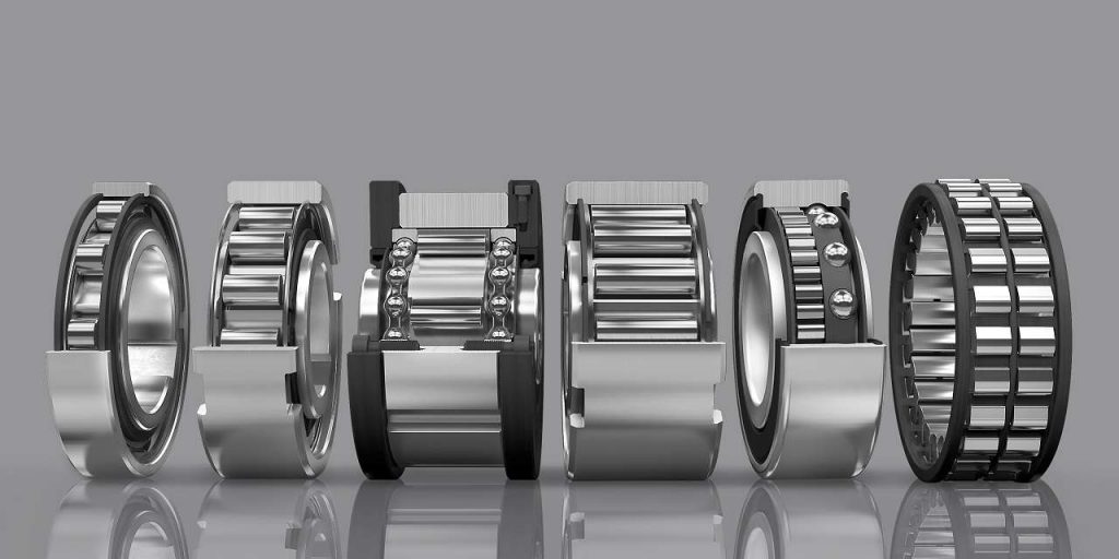
4.Sprag Clutches: Sprag clutches are a type of backstop used to prevent thereverse rotation of a machine or equipment. They consist of a cylindrical outer race andan inner race with sprags (small angled teeth) that engage in one direction but allow freerotation in the opposite direction.
5.Roller Clutches: Roller clutches are another type of backstop that use rollersinstead of sprags to prevent reverse rotation. They are typically used in high-speedapplications and can handle high torque loads.
6.Ratchet and Pawl Mechanisms: Ratchet and pawl mechanisms are used toprevent reverse rotation in low-speed applications. They consist of a ratchet (a toothedwheel) and a pawl (a spring-loaded lever) that engage in one direction but allow freerotation in the opposite direction.
Overall, the choice of coupling or backstop will depend on the specific requirements of the application, such as the amount of misalignment that needs to be compensated for, the amount of torque that needs to be transmitted, and the speed and direction of rotation.

Backstops
Backstops are an essential component in many mechanical systems, particularly those involving rotating machinery. These devices are designed to prevent the reverse rotationof a shaft, and they are commonly used in applications like conveyor systems, cranes, and various types of equipment in the mining and energy industries. In this blog post, we will take a closer look at backstops, how they work, their advantages, and their applications.
How Backstops Work:
Backstops work by using a combination of mechanical and spring-loaded mechanisms to lock the rotational movement of a shaft in one direction. When the shaft rotates in theforward direction, the backstop allows it to pass through freely. However, when theshaft begins to rotate in the opposite direction, the backstop engages and locks it in place, preventing it from rotating any further.
Backstops typically have two main components: the inner and outer races. The innerrace is typically connected to the shaft, while the outer race is stationary. The spring-loaded mechanism is located between these two races, allowing for the backstop toengage or disengage depending on the direction of rotation.
Advantages of Backstops:
Backstops offer several advantages over other types of mechanical systems. Theseinclude:
Applications of Backstops:
Backstops are used in a wide variety of applications, including:
Conclusion:
Backstops are an essential component in many mechanical systems, providing addedsafety, improved efficiency, and durability. They work by using a combination of mechanical and spring-loaded mechanisms to prevent reverse rotation of a shaft. Backstops are used in a variety of applications, including conveyor systems, cranes, theenergy industry, and mining. With their ability to prevent reverse rotation and enhanceoverall system safety and efficiency, backstops are a critical component in many rotatingmachinery applications.
